

|
Car Steering Lock ELV Simulator N360 Emulator for VW Touareg / Phaeton / Audi A8 and Bentley / Porsche Cayenne 00288 Codes

-
- Product Name: Car Steering Lock ELV Simulator N360 Emulator for VW Touareg / Phaeton / Audi A8 and Bentley / Porsche Cayenne 00288 Codes
- Item NO.: Emulator-07
- Weight: 0.5 kg = 1.1023 lb = 17.6370 oz
- Volume: 300 CBM
- Category: Key Programmer > Emulator/ simulator
- Creation Time: 2022-05-23
- Car Steering Lock ELV Simulator N360 Emulator for VW Touareg / Phaeton / Audi A8 and Bentley / Porsche Cayenne 00288 Codes
car Steering Lock ELV Simulator N360 Emulator for VW Touareg / Phaeton / Audi A8 and Bentley / Porsche Cayenne 00288 Codes
Orientation Lock Simulator User Manual
1. Product application
Models such as Cayenne, Phaeton, Audi A8, and Volkswagen Touareg that use the shape of the photo in point 1 and are equipped with the J518 module in point 2 can be replaced by this simulator. The replacement objects are mainly faults such as motor stuck.
Note: If the original car ELV reads a fault code similar to the "unreliable signal" in the figure below in the diagnostic instrument, please do not try to replace the simulator lightly, and be sure to do a good job of confirmation before replacement.


①. This simulator corresponds to the appearance photos of the applicable ELV products:


②. Outline drawing of the J518 anti-theft module matching the above ELV:

③. Photos of ELV internal accessories:
After disassembling the product, pay attention to keep the motor welding seat, plug and CPU indicated by the arrow for spare.


2.Product Introduction of Orientation Lock (ELV) Simulator
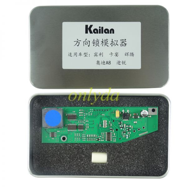
①. Product packaging photos:

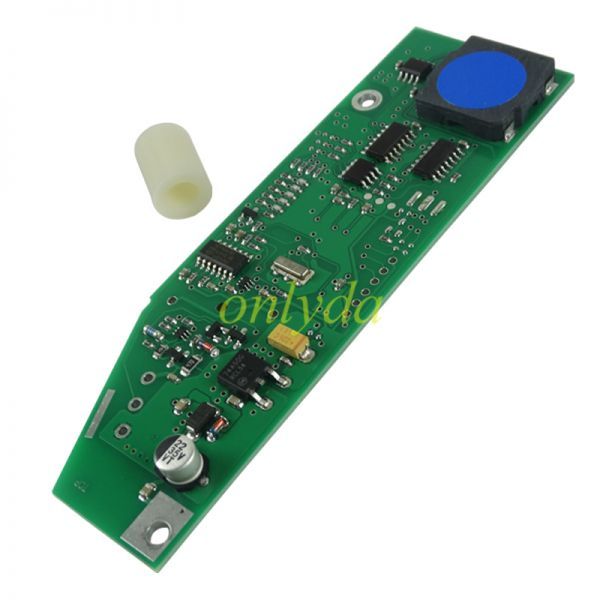
②. The list of items in the package, as shown in the figure below:
Nylon plastic spacer × 1 pc + Orientation lock simulator × 1 pc

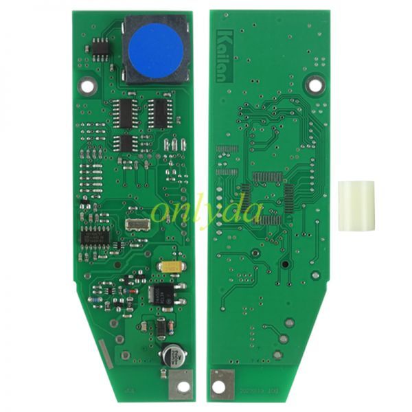
③.Product appearance photos:

3.replacement process
①. Remove the ELV plug and CPU from the original car, and clean up the excess solder, ready for transplantation.

③. Solder the CPU, pay attention to the first pin mark and the direction of the CPU on the original board, as shown in the figure below:
Note: After soldering, please be sure to check the soldering and clean the residual flux paste.


③. Welding plug
Note: Please do not rush to solder the three solder joints after the plug is placed, first confirm the direction and position so that it can be easily installed into the shell.

④. Connect to the car for action test
Note: Before plugging in the plug on the car, please further check the CPU soldering to ensure that there are no problems such as missing soldering, virtual soldering, and continuous soldering, otherwise the CPU may be damaged.
After completing the above checks, connect to the plug, insert the key, and carry out relevant tests. If it works normally, the simulator will emit a sound simulating the action of the lock body when the key is inserted and pulled out. ⑤. Install the nylon plastic pad column
A. First adjust the worm of the motor so that the lock body returns to the lowest end, and pay attention to the position of the protrusion and the spring washer. With the help of a suitable tool, put the bottom side of the plastic pad column against the spring washer, and put it into the groove according to the figure on the right below middle


B. Use a suitable tool to pry the plastic post at the arrow position in the lower left figure, so that it can pass over the protrusion smoothly, and then press the plastic post into place, as shown in the lower right figure after it is in place.


6. Put the tested simulator circuit board into the lock body, pay attention to the welding and screw installation at the position indicated by the arrow in the figure below

You May Also Like
-

-

-

-

-
 Julie Emulator V110 proUS$ 20.00
 -

-

-

-

-

-

-

-

-

-

- Company Info
- Feedback
- Customer Reviews
- About Us
- Contact Us
- News
- User Center
- Forget Password
- My Orders
- Tracking Order
- My Account
- Register
- Payment & Shipping
- Shipping Methods
- Payment Methods
- Terms of Service
- Return Policy
- Privacy Policy
Customer Reviews